Summary
|
The Hydraulic Arm is a hydraulically actuated robotic arm that is theoretically capable of lifting up to 400 lbs. From 2016 to 2018, I developed it with other members of the CCNY Robotics Club.
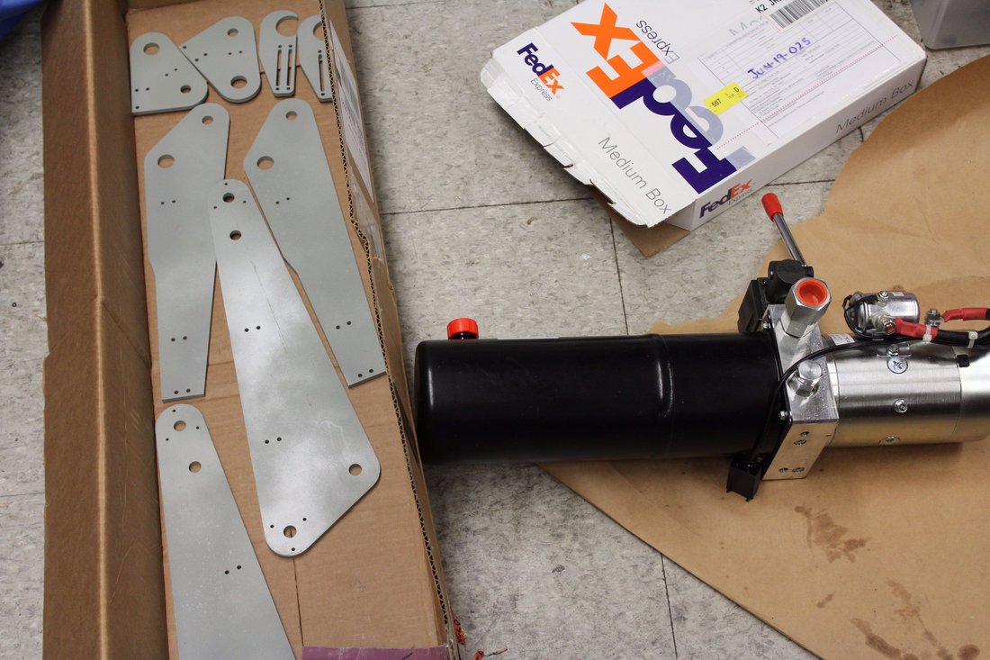
We began the Hydraulic Arm project in order to gain experience with hydraulic systems, as well as force and position control. I was responsible for all of the mechanical design, from the heavy duty worm drive gearbox on the base of the robot to the two cylinder double acting hydraulic circuit. The worm drive gearbox was CNC milled from aluminum, with a COTS worm and gear. Both axial needle roller bearings and ball bearings are used. Relative optical encoders are used on all three joints, and a system of three load cells are used for the "exoskeletal" control mode, in which the user will be able to control the movement of the arm with hand pressure on the end effector. Currently the end effector is just a hook, but it will be replaced with more sophisticated devices such as a gripper once we are out of the initial testing phase. Beaglebone Blue is used as the processor and microcontroller for the brush motor, directional valves, flow control valves and sensors. Separate power supplies are used for the 3000 PSI hydraulic power unit and control electronics. Throughout the 2016-2017 academic year, we designed the mechanical, electrical, and control systems of the arm and machined the gearbox for the electrically powered base. As the 2017-2018 academic year began, we continued to purchase parts from the BoM and began simulating the integrated system using MATLAB Simulink. |
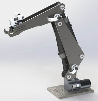
Rendering.
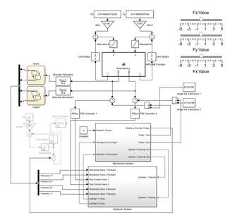
An early Simulink model of the control system.
|
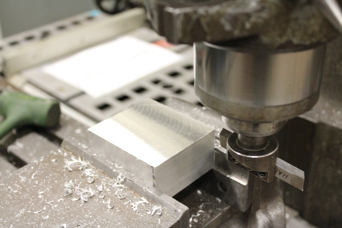
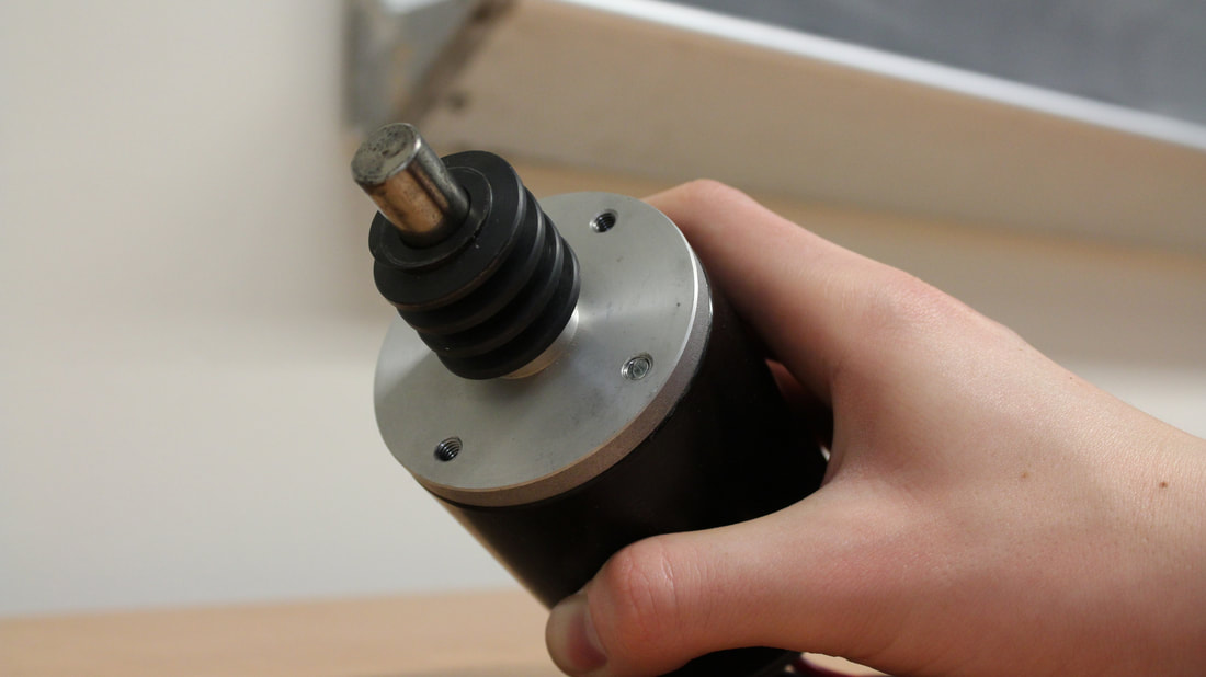
The Gearbox
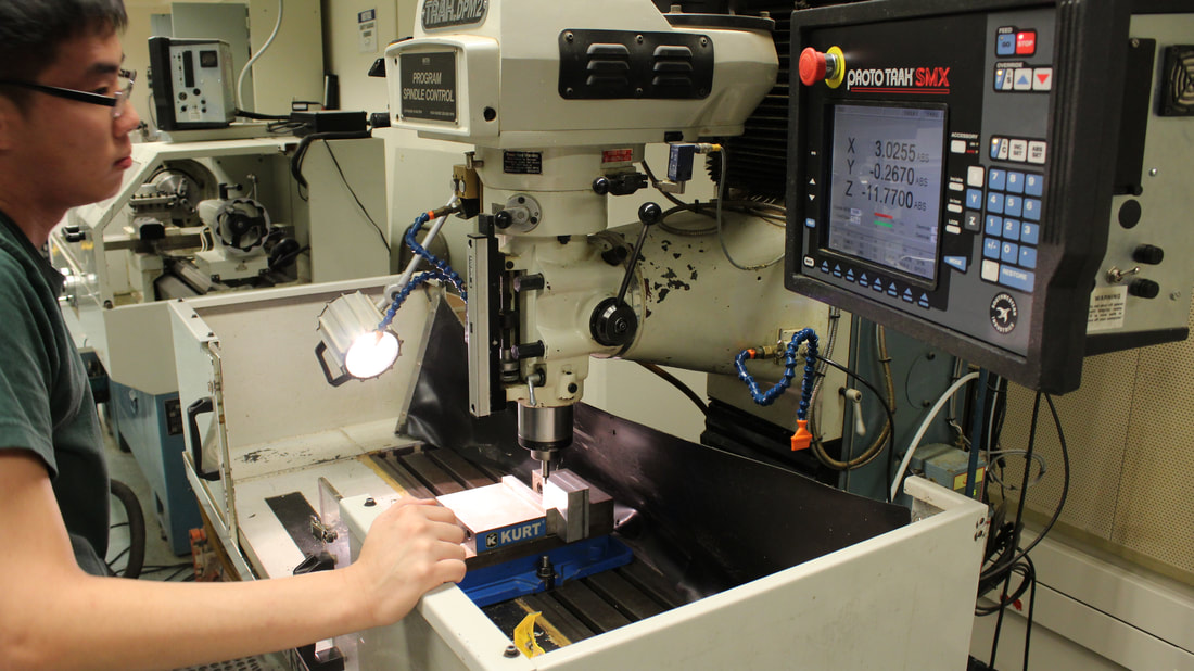
The gearbox was the first part of the robot I manufactured, over the winter break of 2017. It forms the base of the robot, and as such must support all of the load. In order to prevent the entire robot arm from toppling, it is bolted to a steel plate that is clamped to the worktable.
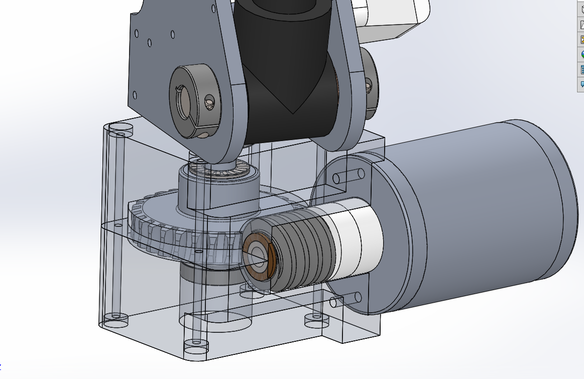

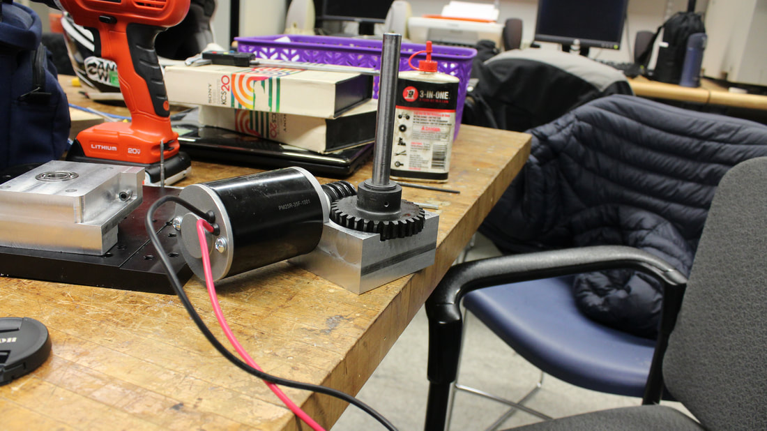
Assembly
|
|
The Control System
After months of teaching myself Simulink, I was able to model the control system for the arm. The block diagram, generated and tested in Simulink, will be converted into C++ code through Simulink Coder, and uploaded to the BeagleBone Blue.
The Simulink Student Challenge is a competition created by Mathworks. I created the video shown below in order to enter this project into the competition.
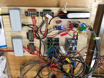
The Electrical System
Many thanks to Leo Strauss, who led the electrical team and did the majority of the electrical design on this project.